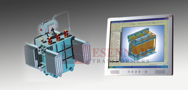


We use customised Pro-E software for designing of Electrical Transformers, 3D view is possible and by given parameters how the transformer will look once manufactured can be simulated. We design as per IS: 2026, IS: 1180, IEC: 60076 & CBIP norms which are followed in the industry. By using the software we can predict how the transformer will behave under electromechanical stresses, short circuits and overloads. The designs are so chosen that the total cost including material, maintenance and the energy cost due to no load and load losses are minimum. The design and manufacturing operations are guided and controlled by experts in the field. All the above factors ensure that transformer is with optimum design, reliable and rugged in construction.
Copper Winding:
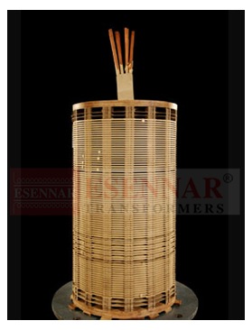
The most significant material in a transformer is the winding which comprises of rectangular and round conductors used for windings. The conductor is usually insulated with either high-grade multi-paper covering or with an insulating enamel coating.
The windings are designed so as to ensure reduced axial stresses during Short Circuit conditions and withstands impulse and over-voltages. Some standard forms of coil winding are Spiral,Helical, Cross-Over and Disc winding. For Power Transformers, both low voltage and high voltage windings are Disc type, which give highest resistance against short circuits. It is ensured proper tension is given on the winding for rigidness.
After receiving Copper conductor it will undergo Quality checking, Conductivity test (Resistance test) and during winding continuity of parallel conductors will also be checked.
Coil Tightening: Winding coils are compressed to the designed heights after the insulation is dried for specified duration to ensure their proper shrinkage to designed level. For higher rating transformers compressing is done by hydraulic press with suitably designed clamping fixtures.